Raspberry Pi 2 #
INPUTs and OUTPUTs #

So far we have looked at INPUTs and OUTPUTs to a microcontroller
An INPUT is a signal we GIVE to the microcontroller. We must provide the voltage to the microcontroller pin. If the input pin is a digital pin the levels are representated as a LOGIC 1 (3.3 V) and LOGIC 0 (0 V). If the input pin is an analog pin the level can vary from 0 V to the maximum voltage the pin can handle. The microcontroller can READ the voltage at this INPUT pin. The microcontroller CANNOT SET this pin to be a voltage since is an INPUT.
For the raspberryPi we use the digitalREAD(pin number/name) function to read a digital input pin. We must give it the pin name or GPIO number.
For example:
digitalRead(15) 	// Reads the level on GPIO 15. If GPIO 15 is LOGIC 1 then a 1 is returned by the function.
digitalRead(LED_PIN) 	// Reads the level on a GPIO called LED_PIN. If it is LOGIC 0 then a 0 is returned by the function.
.
An OUTPUT is a signal that is GENERATED by the microcontroller. If the output pin is a digital pin the levels generated are a LOGIC 1 (3.3 V) and LOGIC 0 (0 V). If the output pin is an analog pin the level can vary from 0 V to the maximum voltage the pin can generate. The microcontroller can SET the voltage at this OUTPUT pin. If it is a digital output we generally say it is a LOGIC 1 (3.3V) or a LOGIC 0 (0 V).
For the raspberryPi we use the digitalWRITE(pin number/name, STATE) function to set a digital output pin to be a LOGIC 1 or a LOGIC 0. We must give it the pin name or GPIO number and the LOGIC level to set the pin to. See the example below.
For example:
digitalWrite(15, HIGH) //Sets the GPIO 15 to be a LOGIC 1.
digitalWrite(LED_PIN, LOW) // Sets a GPIO that was named LED_PIN to a LOGIC 0
A basic example of using INPUTs and an OUTPUT in a microcontroller is shown below. This code mimics a LOGIC AND GATE. Remember you can have multiple outputs and inputs in a circuit. We must define EVERY input and output that the circuit requires and that we intend to use in our code.
|
|
PORTs #
A PORT is a group of inputs or outputs combined to create a multi-bit digital signal.
When we use a single digital GPIO pin it is ONE digital signal. It is either a LOGIC 1 or a LOGIC 0. So, it could be seen as a 1-bit signal.
What if we need to use a signal that has more than 1-bit?
For example, take a 3-bit binary counter. This signal has 3 individual bits that are combined in a specific order to create a binary count. This would require 3 GPIO OUTPUTS to drive 3 individual LEDs.
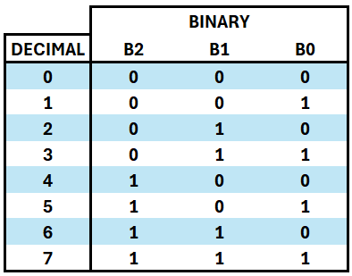
If we were to implement this counter in C code we would need to know the decimal value and then set each individual bit to a LOGIC 1 or LOGIC 0 to represent that value in binary.
If the value was 3 –> we would need to set the 3 GPIO pins to be 0 / 1 / 1.
If the value was 5 –> we would need to set the 3 GPIO pins to be 1 / 0 / 1 and so on for all other values.
This would resut in an IF...ELSE IF strucutre to set all combinations of our counter. That is very tedious and long.
An alternative method is to create a PORT. This is where we can group a number of GPIO pins together in code to represent our binary value.
On the RaspberryPi we can implement a port by using a logical shift operator >>.
There are TWO logical shift operaotrs in C code that we can use:
>>– This represents a logical shift RIGHT<<– This represents a logical shift LEFT
This works by shifting the BINARY representation of the value to the left or right depending on the operator used. To use this in C code it looks like this:
a = 15 >> 2; //This will shift 15 to the right by 2 places and put the result in 'a'
HOW DOES THIS WORK?

The binary bits are moved to the RIGHT if >> is used. Every time it moves to the right, a 0 bit is added to the left of it keeping it as a 4-bit number in this case.
These shift operators are used regularly in microprocesser programming to manipulate values in binary.
To use them to create a PORT see the example below:
|
|
- Remember 5 = 101 in binary.
- LED0 is NOT shifted any places as the bit is already in the position to be applied to the GPIO pin. That is the 1st position.
- LED1 is shifted 1 place to the right as this is the 2nd bit of the number. It needs to be shifted to the 1st location to be applied to the GPIO pin.
- LED2 is shifted 2 places to the right as this is the 3rd bit of the number. It needs to be shifted to the 1st location to be applied to the GPIO pin.
TASK
Put the above code into Geany and verify that you can create a port and create a 3-bit binary number with your RPi.
If you do not have enough LEDs or resistors please ask the lecturer.